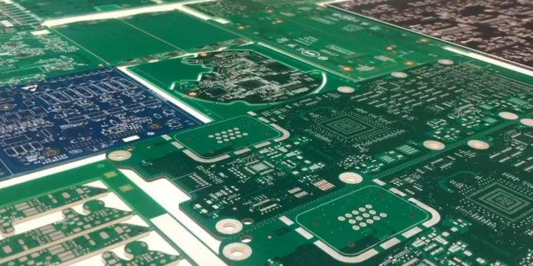
Every person relies on a mini green chip covered with lines and copper parts known as PCB. It is used to connect electronic devices to get current. The electronic signals are transmitted by this prototype circuit board. No one is there who doesn’t want to get the latest and most efficient item from the stock.
How people can close their eyes after viewing the high-frequency PCB? It is designed for 100% accuracy or near about. The specific material and components are used in it to avoid issues and short circuits when it is working on a high frequency. No one will ensure the quality of material rather than CAMTECH PCB!
Scroll down and get more amazing information about the high-frequency board by this brand!
Features of High-Frequency PCB by CAMTECH PCB
The main characteristics of this special kind of PCB are enlisted below after a keen search to help you out!
- The circuits and sub-circuits all are connected by high-speed interfaces.
- The frequency of the digital circuits is so high for efficient performance that it is at least 50MH and higher than it
- The minimum time required for the track integrity in the high-frequency boards is at least 1/3 of the signal propagation time.
- The high-speed interfaces are used in it for fast data transmissions like SATA, USB, PCI Express, Thunderbolt, and HDMI.
Challenges to High-Frequency PCB
Designing a high-frequency circuit board is just like designing something more efficient. When you design an exceptional product, it has to face a few challenges that are given, and CAMTECH considers all of them while designing PCBs!
#1. Coupling
Two conductors close together and cause coupling that has a negative effect on signal propagation. So CAMTECH takes care of it while designing the layout of the PCB.
#2. Signal Degradation
Signal degradation occurs when signals are transmitted for long or mismatched.
#3. Absorption
Your board absorbs the radiations and heat from other boards, reducing the efficiency.
#4. Reflections
The lack of impedance matching is the other reason for poor signal integration that cause reflection of the signals to the source instead of the transmitted place.
#5. Radiations
The radiations are absorbed by the board and cause it to be mounted because these are the wireless devices to transmit or convert digital signals.
#6. Harmonic Distortions
The system is hampered by the frequency shifts that are why the harmonic distortions may cause interrupted signals.
#7. Surface Tracking
The production of current through degradation insulation may cause the problem of surface tracking in high-performance PCBs. The tracking is so dangerous and difficult that it may cause the burning of the components and fire of the devices.
#8. Mode Noise
The stray capacitance between the terminals causes the common mode noise. CAMTECH PCB worked a lot to remove this problem from its products.
#9. Parasitic Capacitance
The unwanted coupling in the board can be due to parasitic capacitance. It can’t be removed permanently, but its effect can be reduced.
Verdict
There is a wide range of technology that is promoting this world day by day. Something new has been launched with every sunrise. Every automated or electronic item is incomplete without PCBs that supply current. There are a few places where you use the high frequency and get some interruptions. Don’t worry, Buddy! High-frequency PCB is designed to solve this kind of issue. If you also want to attain it, contact us whenever you get time!


